Image Based Lighting with Multiple Scattering
August 19, 2019Introduction and Background
Recently I decided to implement image based lighting in BGFX, since I had never done so before and it’s a great way to produce realistic renders with assets authored for PBR. As I started reading I realized that approaches had gotten a lot more involved than they had been even 10 years ago, and that it might be useful to others to have a reference for implementation from start to finish. I’ve documented the steps involved in implementation, starting with some background, then moving onto Karis’s 2014 paper explaining Unreal’s IBL implementation, and then finally new approaches from Fdez-Agüera and others to address the error present in existing models.
Let’s start by defining the equation which defines the outgoing radiance from a point in the viewing direction :
Where is our viewing angle, is our bidirectional reflectance distribution function (BRDF), is the radiance incident on point from direction , and is the normal vector at point . The hemisphere is aligned with , and is the is the halfway vector, halfway between and .
I’ve omitted and as function arguments, but in reality they are also required to evaluate the BRDF. Here’s a diagram of our different vectors:
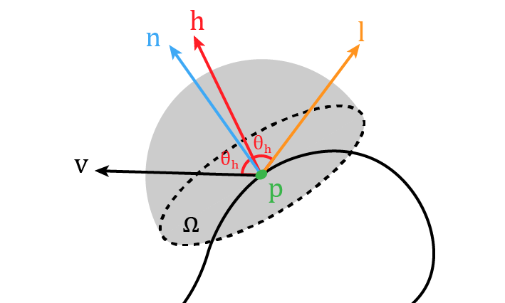
For our BRDF, we will take the popular approach of using a Lambertian diffuse lobe and Cook-Torrance microfacet model for our specular lobe:
Where is our normal distribution function (NDF), which tells us what proportion of our perfectly reflecting microfacets will have normals aligned with , therefore reflecting the light from in the direction . is the Fresnel term which defines what proportion of light is reflected as opposed to refracted into the surface. is the “self shadowing term”, which defines what proportion of our microfacets will be occluded by the surrounding surface along the direction .
For more detail on this model, there are many resources but Naty Hoffman’s talk from this 2013 Siggraph workshop is very helpful in explaining this BRDF if you’ve never seen it before. I’ll also go ahead and define our functions explicitly, to dispell any ambiguity as to which variation we’re using here.
One extremely important detail is that the lobe only accounts for a single scattering of energy. In reality, rougher surfaces will produce multiple scattering events. This is especially important for metals, where reflection dominates. We will see the consequences of only including a single scattering event in our BRDF model later.
For our NDF , we’re using the GGX lobe:
where . Here, , AKA perceptually linear roughness, will be an input into our shading model, stored as a channel in our textures.
Meanwhile, for our geometric shadowing/attenuation term we’re using the height correlated Smith function for GGX:
Note that we’ve expressed this in a way that incorporates the denominator of the BRDF into our term. For more detail on this term, I’ve found this section of the Filament documentation to be helpful.
Finally, our Fresnel term will use the Schlick approximation:
Where is a material property representing the specular reflectance at incident angles (). The second form will come in handy later. For dielectrics, this is taken to be a uniform 4% as per the GLTF spec, while for metals we can use the albedo channel in the texture:
const float DIELECTRIC_SPECULAR = 0.04;
F_0 = lerp(vec3(DIELECTRIC_SPECULAR), albedo.rgb, metalness);
For the constant diffuse term , we’ll be using the GLTF spec for determining , which allows for a single albedo texture used by both metals and dielectrics:
diffuseColor = albedo.rgb * (1 - DIELECTRIC_SPECULAR) * (1.0 - metalness)Image Based Lighting Challenges
Okay, so that’s our BRDF and the reflectance equation we need to evaluate for every pixel covering our mesh. Let’s turn our attention now to the hemisphere we need to integrate across. In order to do so, we need to be able to evaluate for any given . In real time applications, we have two approaches, often used together:
- Describe using a set of analytical lights. Then, we only need to evaluate the integral times, for each corresponding light direction .
- Describe using an environment map, often using a cube map.
We’ll be focused on item 2 in this post. While an environment map can provide much more realistic lighting, the naive evaluation of our hemispherical integral is not going to cut it for interactive computer graphics. To gain a quick understanding of the challenges involved, consider the following:
- With a typical microfacet model we have both specular and diffuse lobes.
- The Lambertian lobe is dependent on light incoming from every part of our hemisphere. We must sample as much of the hemisphere as possible.
- Sampling the hemisphere naively, we’ll need potentially thousands of texture reads.
- For the specular lobe, our roughness will determine what parts of the hemisphere are most important. Other parts will not be as important and will not help us converge on a solution.
- Additionally, each sample will require evaluation of the BRDF, which for the specular component, is not “cheap”.
Performing all of this work with every mesh isn’t feasible for anything but the simplest of scenes. Additionally, sometimes we’ll be redoing work — for instance, calculating the diffuse irradiance for each direction really only needs to happen once for each environment map!
Instead, we’re going to try to pre-compute as many parts of the integral as possible. In order to do so, we’ll need to identify what we can precalculate and have to make some approximations.
Lambertian Diffuse Component
First, since it’s easier, let’s look at the diffuse part of our reflectance integral:
Since our integral is not dependent on any material properties or view direction, and instead dependent only on , we can solve this integral for every direction and store the results in a cube map, allowing us to later look up the irradiance for any normal direction. Note that since we’re not using an NDF, we can get away with simple uniform sampling of our hemisphere.
In BGFX, I implemented this using compute shaders, using thread groups with a third dimension corresponding to the faces of the cube. I’m not certain this is actually a good idea as it may result in poor coherency, but I didn’t have time to benchmark against seperate dispatches for each face. This is left as an exercise for the reader.
Here’s the shader code used to generate a 64x64 irradiance map inside of a compute shader:
#define TWO_PI 6.2831853071795864769252867665590
#define HALF_PI 1.5707963267948966192313216916398

#define THREADS 8

SAMPLERCUBE(s_source, 0);
IMAGE2D_ARRAY_WR(s_target, rgba16f, 1);

NUM_THREADS(THREADS, THREADS, 6)
void main()
{
    const float imgSize = 64.0;
    ivec3 globalId = gl_GlobalInvocationID.xyz;

    vec3 N = normalize(toWorldCoords(globalId, imgSize));

    vec3 up = abs(N.z) < 0.999 ? vec3(0.0, 0.0, 1.0) : vec3(1.0, 0.0, 0.0);
    const vec3 right = normalize(cross(up, N));
    up = cross(N, right);

    vec3 color = vec3_splat(0.0);
    uint sampleCount = 0u;
    float deltaPhi = TWO_PI / 360.0;
    float deltaTheta = HALF_PI / 90.0;
    for (float phi = 0.0; phi < TWO_PI; phi += deltaPhi) {
        for (float theta = 0.0; theta < HALF_PI; theta += deltaTheta) {
            // Spherical to World Space in two steps...
            vec3 tempVec = cos(phi) * right + sin(phi) * up;
            vec3 sampleVector = cos(theta) * N + sin(theta) * tempVec;
            color += textureCubeLod(s_source, sampleVector, 0).rgb * cos(theta) * sin(theta);
            sampleCount++;
        }
    }
    imageStore(s_target, globalId, vec4(PI * color / float(sampleCount), 1.0));
}
Note that you may not need a such a small step size. I was struggling with ringing artifacts with certain environment maps, so I opted to use a smaller delta which helped. Since the operation is done outside the render loop and only once per environment map, I didn’t want to spend too much time tweaking performance.
Importance Sampling
In order to integrate the specular part of our radiance equation, we’ll need to use importance sampling, using the following equation:
Where is the probability distribution function we use for sampling our hemisphere. Intuitively, the idea behind having the PDF in the denominator is that if a direction is more likely to be sampled than others, it should contribute less to the sum than a direction that is very unlikely to be sampled.
We could naively sample our hemisphere randomly, but at low roughness our specular component will converge to the actual solution very slowly. The same is true if we attempt to sample our hemisphere uniformly. To reason about this, consider a roughness close to zero, which corresponds to a perfect reflector. In this case, the only light direction that matters is the direction of perfect reflection from based on . Every other direction will contribute nothing to our sum. And if we do manage to sample , we still won’t converge due to the term. At hight roughness, this is less of a factor as the distribution of our microfacet normals will increase, and we’ll have to consider most parts of our hemisphere.
Instead, we’ll choose a PDF that resembles our BRDF in order to decrease the variance. We can use our Normal Distribution Function as our PDF, the reasoning being that the NDF determines which directions contribute the most to the light leaving our larger surface patch. More correctly, we’ll actually be sampling , since this is how the normal distribution is actually defined:
If we want our PDF to be used for instead of the half vector then we’ll need to include the Jacobian of the transformation from half vector to , :
You can also read section 5.3 of Walter et al. 2007, as well as Legarde et al’s course notes for more detail.
It’s also worth noting that we won’t be sampling directly and instead we’ll sample our microfacet normal and use it to find the relevant . To do so, we’ll need to map two uniformly random variables in the interval , let’s call them , to and in spherical coordinates. Then, we can turn our into a cartesian direction in world space. We can then use this to find to sample our environment map to evaluate .
The mapping from to and won’t be derived here, but Tobias Franke and A Graphics Guy have good blog posts that break this down step by step. Ultimately the mapping is as follows:
Note that this mapping assumes we’re restricting ourselves to an isotropic version of the GGX, which is why the term is just randomly sampled. You may also notice the term in our equation for , but it may not be obvious how this dependency causes the equation to behave. I created a Desmos demo that you can play around with to get a sense of how this maps our to . Observe that at low roughness, most of the range will map to a small , while for greater roughness we approach a standard cosine distribution, and we’re much more likely to get directions “further” from .
With this mapping we now have a method of importance sampling our hemisphere that will drastically improve convergence. Here’s some GLSL code that shows how we could sample a quasi-random direction :
// Taken from https://github.com/SaschaWillems/Vulkan-glTF-PBR/blob/master/data/shaders/genbrdflut.frag
// Based on http://holger.dammertz.org/stuff/notes_HammersleyOnHemisphere.html
vec2 hammersley(uint i, uint N)
{
    uint bits = (i << 16u) | (i >> 16u);
    bits = ((bits & 0x55555555u) << 1u) | ((bits & 0xAAAAAAAAu) >> 1u);
    bits = ((bits & 0x33333333u) << 2u) | ((bits & 0xCCCCCCCCu) >> 2u);
    bits = ((bits & 0x0F0F0F0Fu) << 4u) | ((bits & 0xF0F0F0F0u) >> 4u);
    bits = ((bits & 0x00FF00FFu) << 8u) | ((bits & 0xFF00FF00u) >> 8u);
    float rdi = float(bits) * 2.3283064365386963e-10;
    return vec2(float(i) /float(N), rdi);
}

// Based on Karis 2014
vec3 importanceSampleGGX(vec2 Xi, float roughness, vec3 N)
{
    float a = roughness * roughness;
    // Sample in spherical coordinates
    float phi = 2.0 * PI * Xi.x;
    float cosTheta = sqrt((1.0 - Xi.y) / (1.0 + (a * a - 1.0) * Xi.y));
    float sinTheta = sqrt(1.0 - cosTheta * cosTheta);
    // Construct tangent space vector
    vec3 H;
    H.x = sinTheta * cos(phi);
    H.y = sinTheta * sin(phi);
    H.z = cosTheta;

    // Tangent to world space
    vec3 upVector = abs(N.z) < 0.999 ? vec3(0.0, 0.0, 1.0) : vec3(1.0, 0.0, 0.0);
    vec3 tangentX = normalize(cross(upVector, N));
    vec3 tangentY = cross(N, tangentX);
    return tangentX * H.x + tangentY * H.y + N * H.z;
}
One thing in the above code I did not touch on at all is the Hammersley sequence, which is the method by which we create our random numbers . It’s a low-discrepancy sequence that I won’t do any justice describing, so here’s a wikipedia link.
We can further improve the rate of convergence by filtering our samples as well. The idea is described in detail in Křivánek and Colbert’s GPU Gems article which I will briefly summarize. When using our importance sampling routine, we evaluate the PDF value for the sample and if it is “small” then this corresponds to a direction we sample infrequently. To improve convergence, we can consider this equivalent to sampling a larger solid angle in our hemisphere. The inverse is also true: samples with higher PDF values will correspond to smaller solid angles. But how do we sample a larger or smaller solid angle in our environment without having to integrate? The solution is to approximate this by sampling the mip chain of our environment map! It’s a very clever trick, and drastically improves convergence. You’ll see it demonstrated in some shader code later on.
Now that we can importance sample our hemisphere, we can turn our attention back to the radiance equation and see which parts we can calculate and store to cut down on the amount of work we need to do for each frame.
Split Sum Approximation
In Karis’s presentation of the Unreal Engine PBR pipeline, he explains that we can actually approximate the specular part of our radiance sum by splitting it in two:
As Karis notes, this approximation is exact for a constant term, and reasonable for “common environments”. This approximation enables us to store the two different sums separately. Let’s examine each sum:
Pre-filtered Environment Map
The first sum is what’s commonly referred to as the “pre-filtered environment map” or just the “radiance map” in other papers. When we say “pre-filtering”, what we’re actually doing is evaluating and storing a value such that when we go to render our mesh, we can simply sample this stored value to obtain . The idea is that we can skip having to integrate across our hemisphere in order to figure out the radiance reflected in , and instead just look it up in a prefiltered cube map.
Interestingly, Karis and others convolve this sum with the GGX by still using the GGX based importance sampling. This improves convergence, which is important if you’re planning on having your environment map change over time and need to re-evaluate it outside the context of an offline pipeline. So really, we’ll be performing the following sum instead of the one above:
Karis doesn’t provide any mathematic justification for the additional summation in the denominator, or why we should evaluate by importance sampling GGX, but as noted by Sebastian Legarde (pg. 64) these empirical terms seem to provde the best correction for our split sum approximation for a constant .
However, one big problem with this is that the GGX NDF is dependent on — which creates “stretchy” reflections. Karis approximates the NDF as isotropic where . This is a much larger source of error than the split sum, and is demonstrated by the figure below, which was taken from the previously mentioned Moving Frostbite to PBR course notes:
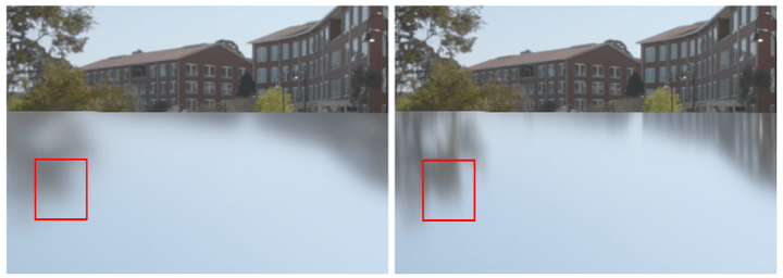
Notice how we lose the stretch reflections visible in the ground truth render on the right once we assume . While the error is large, it’s the price we must pay to be able to perform this sum outside of our render loop when is known.
When it comes to storing the pre-filtered environment map, it’s important to note once again that we’re creating a different map for different roughness levels of our choosing. Since we’ll lose high frequency information as roughness increases, we can actually use mip map layers to store the filtered map, with higher roughnesses corresponding to higher mip levels.
Once again we can compute shaders, with a different pass for each roughness/mip level. Here’s the loop used in the application code to issue each dispatch call:
// width is the width/length of a single face of our cube map
float maxMipLevel = bx::log2(float(width));
for (float mipLevel = 0; mipLevel <= maxMipLevel; ++mipLevel)
{
    uint16_t mipWidth = width >> uint16_t(mipLevel);
    float roughness = mipLevel / maxMipLevel;
    float params[] = { roughness, mipLevel, float(width), 0.0f };
    bgfx::setUniform(u_params, params);
    // Bind the source using a Sampler, so we don't have to perform the cube mapping ourselves
    bgfx::setTexture(0, u_sourceCubeMap, sourceCubeMap);
    // Set the image using a specific mipLevel
    bgfx::setImage(1, filteredCubeMap, uint8_t(mipLevel), bgfx::Access::Write, bgfx::TextureFormat::RGBA16F);
    // Dispatch enough groups to cover the entire _mipped_ face
    bgfx::dispatch(view, preFilteringProgram, mipWidth / threadCount, mipWidth / threadCount, 1);
}
Then our compute shader looks like the following:
#define THREADS 8
#define NUM_SAMPLES 64u

// u_params.x == roughness
// u_params.y == mipLevel
// u_params.z == imageSize
uniform vec4 u_params;

SAMPLERCUBE(s_source, 0);
IMAGE2D_ARRAY_WR(s_target, rgba16f, 1);

// From Karis, 2014
vec3 prefilterEnvMap(float roughness, vec3 R, float imgSize)
{
    // Isotropic approximation: we lose stretchy reflections :(
    vec3 N = R;
    vec3 V = R;

    vec3 prefilteredColor = vec3_splat(0.0);
    float totalWeight = 0.0;
    for (uint i = 0u; i < NUM_SAMPLES; i++) {
        vec2 Xi = hammersley(i, NUM_SAMPLES);
        vec3 H = importanceSampleGGX(Xi, roughness, N);
        float VoH = dot(V, H);
        float NoH = VoH; // Since N = V in our approximation
        // Use microfacet normal H to find L
        vec3 L = 2.0 * VoH * H - V;
        float NoL = saturate(dot(N, L));
        // Clamp 0 <= NoH <= 1
        NoH = saturate(NoH);

        if (NoL > 0.0) {
            // Based off https://developer.nvidia.com/gpugems/GPUGems3/gpugems3_ch20.html
            // Typically you'd have the following:
            // float pdf = D_GGX(NoH, roughness) * NoH / (4.0 * VoH);
            // but since V = N => VoH == NoH
            float pdf = D_GGX(NoH, roughness) / 4.0 + 0.001;
            // Solid angle of current sample -- bigger for less likely samples
            float omegaS = 1.0 / (float(NUM_SAMPLES) * pdf);
            // Solid angle of texel
            float omegaP = 4.0 * PI / (6.0 * imgSize * imgSize);
            // Mip level is determined by the ratio of our sample's solid angle to a texel's solid angle
            float mipLevel = max(0.5 * log2(omegaS / omegaP), 0.0);
            prefilteredColor += textureCubeLod(s_source, L, mipLevel).rgb * NoL;
            totalWeight += NoL;
        }
    }
    return prefilteredColor / totalWeight;
}

// Notice the 6 in the Z component of our NUM_THREADS call
// This allows us to index the faces using gl_GlobalInvocationID.z
NUM_THREADS(THREADS, THREADS, 6)
void main()
{
    float mipLevel = u_params.y;
    float imgSize = u_params.z;
    float mipImageSize = imgSize / pow(2.0, mipLevel);
    ivec3 globalId = ivec3(gl_GlobalInvocationID.xyz);

    if (globalId.x >= mipImageSize || globalId.y >= mipImageSize)
    {
        return;
    }

    vec3 R = normalize(toWorldCoords(globalId, mipImageSize));

    // Don't need to integrate for roughness == 0, since it's a perfect reflector
    if (u_params.x == 0.0) {
        vec4 color = textureCubeLod(s_source, R, 0);
        imageStore(s_target, globalId, color);
        return;
    }

    vec3 color = prefilterEnvMap(u_params.x, R, imgSize);
    // We access our target cubemap as a 2D texture array, where z is the face index
    imageStore(s_target, globalId, vec4(color, 1.0));
}
I also wrote a small ShaderToy example that lets you visualize this for different levels of roughness. The mouse allows you to change the roughness amount. Let’s take a look at the resulting output for the Pisa environment map:
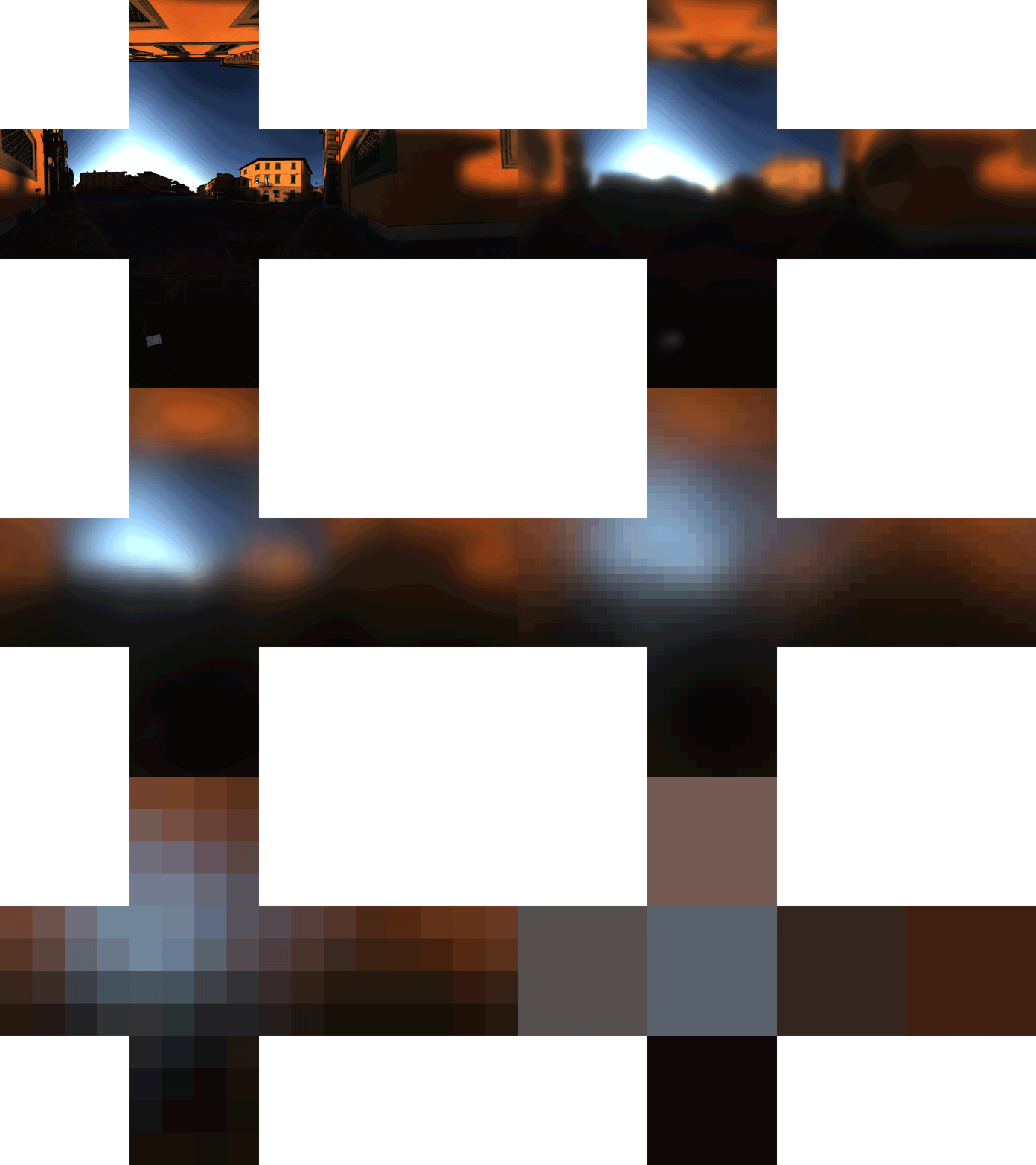
Note that this is in linear space and will appear darker than it would otherwise when rendered properly with the appropriate gamma transformation applied. The size of the mips has been scaled to match the original image size. Also note that the banding is due to GIF encoding, and you shouldn’t see anything like that in your output.
Environment BRDF
Okay, so that’s one sum taken care of, let’s look at the second sum. Once again, our goal here is to try and pre-calculate as much of this sum as possible and store it, allowing us to resolve the radiance equation without having to perform hundreds of texture lookups.
Let’s take a look at it with our specular BRDF and the subbed in:
At this point, we’ve managed to factor out the NDF but our sum is still dependent on both , (through the term) and (through the Fresnel term). The term is particularly inconvenient, because each material will have a potentially different term but we don’t want to have to store a different LUT for each material. However, if we substitute our Schlick’s Fresnel equation and rearrange our terms, we get:
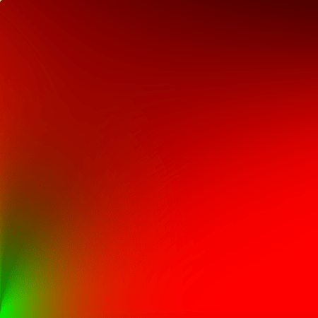
Where are the scale and the bias terms applied to . You may ask yourself what we have accomplished by doing all this, but notice that the only terms outside the sum are dependent on are (through ) and . For we’ll set it to some constant (like the positive z-direction). We can then create a two dimensional LUT where the x-axis is and the y-axis is . The red channel of this LUT will be while the green channel will be .
I used a compute shader that runs once and the resulting LUT is stored in a RG16F texture. Here’s the compute shader code to perform the calculation:
#include "bgfx_compute.sh"
#include "pbr_helpers.sh"

#define GROUP_SIZE 256
#define THREADS 16

IMAGE2D_WR(s_target, rg16f, 0);

// From the filament docs. Geometric Shadowing function
// https://google.github.io/filament/Filament.html#toc4.4.2
float V_SmithGGXCorrelated(float NoV, float NoL, float roughness) {
    float a2 = pow(roughness, 4.0);
    float GGXV = NoL * sqrt(NoV * NoV * (1.0 - a2) + a2);
    float GGXL = NoV * sqrt(NoL * NoL * (1.0 - a2) + a2);
    return 0.5 / (GGXV + GGXL);
}

// Karis 2014
vec2 integrateBRDF(float roughness, float NoV)
{
	vec3 V;
    V.x = sqrt(1.0 - NoV * NoV); // sin
    V.y = 0.0;
    V.z = NoV; // cos

    // N points straight upwards for this integration
    const vec3 N = vec3(0.0, 0.0, 1.0);

    float A = 0.0;
    float B = 0.0;
    const uint numSamples = 1024;

    for (uint i = 0u; i < numSamples; i++) {
        vec2 Xi = hammersley(i, numSamples);
        // Sample microfacet direction
        vec3 H = importanceSampleGGX(Xi, roughness, N);

        // Get the light direction
        vec3 L = 2.0 * dot(V, H) * H - V;

        float NoL = saturate(dot(N, L));
        float NoH = saturate(dot(N, H));
        float VoH = saturate(dot(V, H));

        if (NoL > 0.0) {
            // Terms besides V are from the GGX PDF we're dividing by
            float V_pdf = V_SmithGGXCorrelated(NoV, NoL, roughness) * VoH * NoL / NoH;
            float Fc = pow(1.0 - VoH, 5.0);
            A += (1.0 - Fc) * V_pdf;
            B += Fc * V_pdf;
        }
    }

    return 4.0 * vec2(A, B) / float(numSamples);
}


NUM_THREADS(THREADS, THREADS, 1)
void main()
{
    // Normalized pixel coordinates (from 0 to 1)
    vec2 uv = vec2(gl_GlobalInvocationID.xy + 1) / vec2(imageSize(s_target).xy);
    float mu = uv.x;
    float a = uv.y;


    // Output to screen
    vec2 res = integrateBRDF(a, mu);

    // Scale and Bias for F0 (as per Karis 2014)
    imageStore(s_target, ivec2(gl_GlobalInvocationID.xy), vec4(res, 0.0, 0.0));
}
This shader is a bit simpler than the last, since we don’t have to write to a cube map this time. I’ve written a ShaderToy for this example as well, which shows you what the output looks like. Note that these outputs will be in RGBA8, and aren’t suitable for direct use (i.e. you can’t use the screen cap as an LUT). The two values vary smoothly allowing us to get away with a fairly small LUT. In my BGFX code I store it in 128x128 texture.
Single Scattering Results
Now that we have a prefiltered environment map and a LUT for most parts of our BRDF, and our diffuse irradiance map, all we have to do is put it together.
Where are the values stored in our lookup table, is the prefiltered environment map, is the irradiance map, and are material properties for specular color and diffuse color respectively. Here’s the fragment shader code as well:
$input v_position, v_normal, v_tangent, v_bitangent, v_texcoord

#include "../common/common.sh"
#include "pbr_helpers.sh"

#define DIELECTRIC_SPECULAR 0.04

// Scene
uniform vec4 u_envParams;
#define numEnvLevels u_envParams.x

uniform vec4 u_cameraPos;

// Material
SAMPLER2D(s_diffuseMap, 0);
SAMPLER2D(s_normalMap, 1);
SAMPLER2D(s_metallicRoughnessMap, 2);

// IBL Stuff
SAMPLER2D(s_brdfLUT, 3);
SAMPLERCUBE(s_prefilteredEnv, 4);
SAMPLERCUBE(s_irradiance, 5);

void main()
{
    mat3 tbn = mat3FromCols(
        normalize(v_tangent),
        normalize(v_bitangent),
        normalize(v_normal)
    );
    vec3 normal = texture2D(s_normalMap, v_texcoord).xyz * 2.0 - 1.0;
    normal = normalize(mul(tbn, normal));

    vec3 viewDir = normalize(u_cameraPos.xyz - v_position);
    vec3 lightDir = reflect(-viewDir, normal);
    vec3 H = normalize(lightDir + viewDir);
    float VoH = clampDot(viewDir, H);
    float NoV = clamp(dot(normal, viewDir), 1e-5, 1.0);

    vec4 baseColor = texture2D(s_diffuseMap, v_texcoord);
    vec3 OccRoughMetal = texture2D(s_metallicRoughnessMap, v_texcoord).xyz;
    float roughness = max(OccRoughMetal.y, MIN_ROUGHNESS);
    float metalness = OccRoughMetal.z;

    // From GLTF spec
    vec3 diffuseColor = baseColor.rgb * (1.0 - DIELECTRIC_SPECULAR) * (1.0 - metalness);
    vec3 F0 = mix(vec3_splat(DIELECTRIC_SPECULAR), baseColor.xyz, metalness);

    // Load env textures
    vec2 f_ab = texture2D(s_brdfLUT, vec2(NoV, roughness)).xy;
    float lodLevel = roughness * numEnvLevels;
    vec3 radiance = textureCubeLod(s_prefilteredEnv, lightDir, lodLevel).xyz;
    vec3 irradiance = textureCubeLod(s_irradiance, normal, 0).xyz;

    vec3 FssEss = F0 * f_ab.x + f_ab.y;
    gl_FragColor = FssEss * radiance + diffuseColor * irradiance;
}
Let’s take a look at the results! Here’s a render of spheres of increasing roughness (from left to right) that uses the Pisa courtyard environment map:

We can see how as the roughness increases, we’re using our blurrier prefiltered environment maps. However, you may also be able to notice that as roughness increases, the metal spheres become darker. One way we can demonstrate this fully is to render the spheres in a totally uniform environment, where for all directions . This is also commonly referred to as a “furnace test”:

Here the darkening is much more pronounced. About 40% of the energy is being lost, but since our spheres have a “white” albedo, this is violating conservation of energy. Recall that our model is simply a first order approximation which includes only the single scattering events. In reality, light will scatter several times across the surface, as this diagram from Heitz et al, 2015 illustrates:

As the material becomes rougher, the multiscattering events account for a larger proportion of the reflected energy, and our approximation breaks down. So we need some way of recovering this lost energy if we want to have more plausible results.
Accounting for Multiple-Scattering
Luckily for us, there’s been a significant amount of work done on improving this approximation by accounting for the additional scattering events. Heitz et al. presented their work on modelling the problem as a free-path problem, validating their results by simulating each successive scattering event across triangular meshes using ray tracing. However, their work is too slow for production path tracing, nevermind real time interactive graphics.
Following this, Kulla and Conty presented their own alternative to recovering the energy based on the furnace test, but it requires additional 2D and 3D LUTs and was written in the context of path tracing. Additionally, Emmanuel Turquin built upon the Heitz paper to model the additional scattering events by noting that Heitz’s paper showed the additional scattering events to have lobes resembling smaller versions of the first event’s lobe.
Unfortunately none of these solutions were designed as real time techniques, but just this year Fdez-Agüera published a paper outlining how we could extend the methods outlined by Karis without having to introduce any additional LUTs or parameters. The paper provides a full mathematical derivation, but I’ll try to provide the highlights.
Metals
First, let’s consider a perfect reflector with no diffuse lobe, where . In this case, the total amount of energy reflected regardless of number of bounces must always be equal to the incident energy (due to conservation of energy):
Where is our directional albedo, but with :
To define , we can express it in the same fashion, but with an unknown BRDF:
So we could effectively add this additional lobe to our reflectance equation:
We’ve already discussed the integral on the left, so let’s focus instead on the second integral. We’ll once again use the split sum introduced by Karis, but here Fdez-Agüera makes the assumption that we can consider the secondary scattering events to be mostly diffuse, and therefore use irradiance as a solution to the integral:
Fdez-Agüera further notes that this approximation fails for narrow lights, such as analytical point or directional lights. Interestingly, Stephen McAuley made the clever observation that this multiscattering term will only dominate at higher roughnesses, where our radiance map is going to be highly blurred and fairly diffuse. His comparison shows little difference, so if you weren’t previously using irradiance you could potentially skip it here as well. However we’ve already created our irradiance map, so we will be using it again here.
If we use the approximation from earlier for the single scattering event, and bring in this approximation for the multiscattering event, we end up with the following:
Where are the scale and bias terms from Karis that we’ve stored in our LUT.
Recall, however, that so far we’ve constrained ourselves to a perfectly reflecting metal. In order to extend it to generic metals, we need to re-introduce . Like others, Fdez-Agüera splits into two terms, and such that:
However, unlike previously, we cannot simply set . Instead, Fdez-Agüera models as a geometric series such that:
Where and are defined as:
You’ll have to check the papers for the details on this I’m afraid, as I don’t want to entirely reproduce the paper in this blog post. The conclusion is that we can therefore write our equation for as the following:
Let’s take a second and look at some renders of metals with this new formulation. For the furnace test, we should not be able to see the spheres at all. Below is a comparison between the single scattering BRDF and multiple scaterring BRDF inside the furnace:

Sure enough, using our multiple scattering BRDF we can’t see the spheres at all! The approximation is perfect for constant environments like the furnace, so let’s take a look at a less optimal case:

The improvement is considerable, as roughness does not darken the spheres.
One important thing to mention is that for colored metals, you’ll see an increase in saturation at the higher roughnesses not unlike what Heitz, Kulla and Conty and Hill see. Whether this is desired behaviour is up to you. It appears Turqin’s method does not produce these shifts in saturation, so that is worth investigation if increased saturation is to be avoided.
Dielectrics
So far, we haven’t talked about how our diffuse component fits into this at all. Let’s first examine how dielectrics behave in the furnace test for single scattering by revisting our render from earlier:

At lower roughnesses the Fresnel effect is too strong, and there is still some darkening at higher roughnesses.
This approximation ignores some of the physical reality of diffuse transmission and re-emission, but Fdez-Agüera makes a good argument for why we can keep ignoring them:
It doesn’t explicitly model the effects of light scattering back and forth between the diffuse and specular interfaces, but since specular reflectance is usually quite low and unsaturated for dielectrics, radiated energy will eventually escape the surface unaltered, so the approximation holds. (p. 52)
To extend to non-white dielectrics, we can simply multiply it by the diffuse albedo, .
Let’s look at our final results using the same comparison as before, but with dielectrics this time:

Interestingly, I actually get a darker result with multiple scattering than with single scattering. I’m not totally convinced that this isn’t some subtle bug in my implementation of the dielectric part of the BRDF. However, the significant excess energy at lower roughnesses that we observed with the single scattering BRDF is not present with our new BRDF. Here’s a final render using the Pisa environment, as before, but this time with our new BRDF:


Roughness Dependent Fresnel
In the Fdez-Agüera paper’s sample GLSL code, the author includes a modification to the Fresnel term:
vec3 Fr = max(vec3_splat(1.0 - roughness), F0) - F0;
vec3 k_S = F0 + Fr * pow(1.0 - NoV, 5.0);
// Typically, simply:
// vec3 FssEss = F_0 * f_ab.x + f_ab.y;
vec3 FssEss = k_S * f_ab.x + f_ab.y;
Unfortunately, I haven’t been able to track down the origin of this modification, and it’s not expanded upon in the paper. It doesn’t make much difference when rendering our spheres, especially in the furnace test, but when rendering more complex objects the difference is noticable. To reason about what this term does exactly, I’ve made a little desmos graph demo. You can adjust the term to see how the modification deviates from the Schlick approximation for different levels of roughness. Interestingly, this makes the ramp start earlier for lower roughness levels. I can see this change being plausible: for rougher surfaces, the proprtion of microfacets contributing to the angle dependent Fresnel will decrease. At least that’s the best explanation I could come up with. If you know the reasoning or source for this modification, please let me know!
Here’s a series of renders for you to compare, using the Flight Helmet model. The roughness dependent Fresnel displays the increase in reflections for smoother surfaces like the leather cap and wooden base.
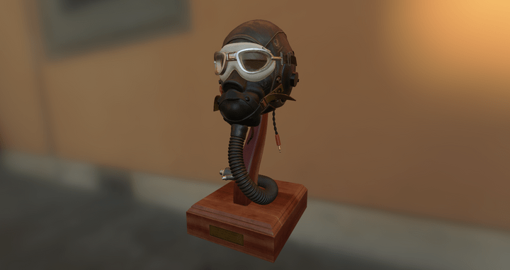
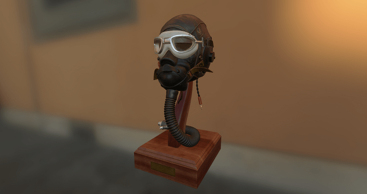
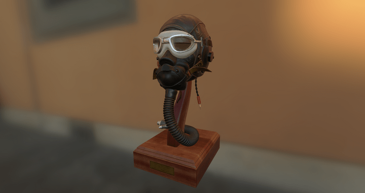
You can also see the brightening of the metal goggles and base’s metal plaque, but otherwise this model is mostly composed of dielectric materials and so the difference is not as large.
GLSL Shader Code
Here’s the multiscattering code, which can be appended to the shader code we used for single scattering above. We are still only using the BRDF LUT, prefitlered environment map, and irradiance map as uniforms; there are no additional uniforms introduced by multiple scattering.
// Same code as from earlier... no extra uniforms

void main()
{
    // Same code from earlier ...

    // Roughness dependent fresnel, from Fdez-Aguera
    vec3 Fr = max(vec3_splat(1.0 - roughness), F0) - F0;
    k_S = F0 + Fr * pow(1.0 - NoV, 5.0);

    vec3 FssEss = k_S * f_ab.x + f_ab.y;

    // Multiple scattering, from Fdez-Aguera
    float Ems = (1.0 - (f_ab.x + f_ab.y));
    vec3 F_avg = F0 + (1.0 - F0) / 21.0;
    vec3 FmsEms = Ems * FssEss * F_avg / (1.0 - F_avg * Ems);
    vec3 k_D = diffuseColor * (1.0 - FssEss - FmsEms);
    vec3 color = FssEss * radiance + (FmsEms + k_D) * irradiance;

    gl_FragColor = vec4(color, baseColor.w);
}
Notice how little code has been added for calculating the new terms! And yet the results for metals are very noticable.
Future Work
- The multiscattering BRDF I’ve implemented here is only presented for image based lighting. McAuley goes into some detail on how it could be extended for area lights using Heitz’s linearly transformed cosine approach.
-
My model doesn’t fully support the GLTF material spec.
I still need to add better support for Occlusion, Emissive, scaling factors and non-texture uniforms (baseColorfor instance can be encoded as a singlevec4). I’m trying to accomplish this piecemeal while implementing other algorithms.- Since writing this post, I’ve added support for all the material properties that the GLTF spec provides in the “roughness metallic” workflow. There is no skinning or animation support yet though.
- For our prefiltered environment map, at lower roughness values we are likely to encounter substantial aliasing in the reflections as we can no longer use the cube map’s mip map chain as we typically would. I’ve seen some implementations like Babylon.js actually just use the higher roughness (e.g. blurrier) parts of the map anyway, to reduce aliasing.
- If you have any feedback, please let me know either using the comments below, my email or my twitter account
Source Code
While I’ve included most of the shader code used, the entire example is available here as 04-pbl-ibl. Note however that it uses non-standard GLTF files, that have had their web-compatible textures swapped out with corresponding DDS files that contain mip maps, generated using the texturec tool provided as part of BGFX. BGFX does not provide an easy way to invoke the equivalent of glGenerateMipmap, so I’ve created a python script to pre-process the GLTF files. It can be found in the scripts folder of the repo.
Comments powered by Talkyard.